
Complex management


As customers move from technology demonstrators through to prototypes and onto production, new functions and features are being demanded to maximise the longevity and performance of the battery pack.

  • Configurability, – With each battery pack configuration comes a set of parameters that need to be optimally managed. One obvious way of doing this is to rewrite the BMS firmware each time.
  • Warrantability, – The BMS needs to log events such as charge/discharge cycles, system errors and faults so that in the event of a problem with the battery pack it can be quickly established whether misuse is a factor and the nature of the problem observed.
  • Load control based on battery condition, – By transmitting allowable discharge and charge rates continuously for the battery, the load can match its power requests to ensure that the battery is always operated within its optimal window of operation. The main condition parameters here are temperature and SoC.
  • Enhanced SoC estimation, – Basic systems use voltage to estimate SoC, this is insufficient given the changes in voltage that occur with load and more importantly, the extremely flat discharge curve of LFP (LiFePO4) chemistries. A better estimate can be achieved by counting the coulombs discharged from the pack and comparing this with the known capacity from the charge cycle. This can be further enhanced by correcting the coulomb counting algorithm to compensate for cell temperature and rate of discharge.
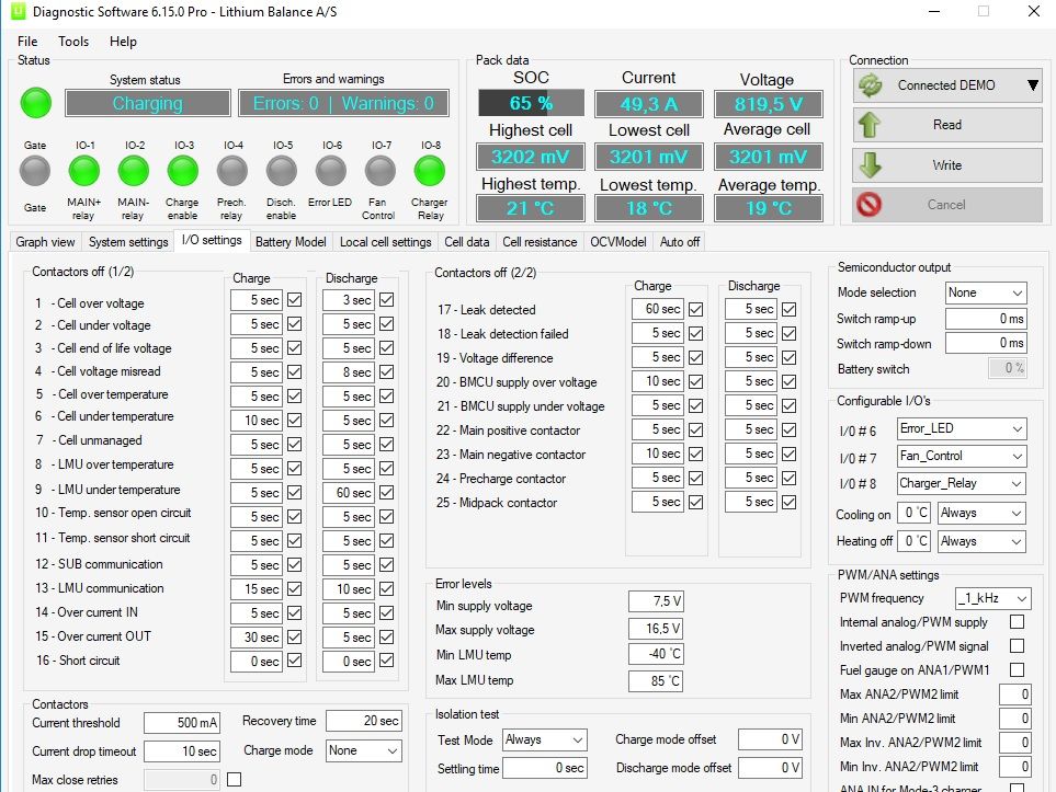
  • Inputs/Outputs from other peripherals, – This can involve controlling cooling circuits, reacting on crash sensors or working with an interlock loop of some type.
  • When discussing costs, many think about the initial development costs and the piece part costs in production, while overlooking the cost of implementation which can be significant if the BMS needs new firmware written by specialists each time.

Complex problem, simple solution

With our latest release, Firmware Type 20000 02. 05, or Sputnik 5 as we like to call it in (Jan 2011) our goal was simple: Make a BMS that possesses the features listed above but can be fully configured without the need for programming skills or specialist programming tools beyond the PC software available with our system.
By giving key elements such as:

  • Pack and cell setup, CAN communication, charger configuration, error logging, contactor switching and battery model, their own easy to use configuration interfaces, it is now very easy to configure the system for any pack configuration and Lithium Ion cell chemistry.
  • Interfacing the system to the load is done typically via the CAN bus and this has been further simplified as you can define up to 7 CAN messages with your chosen frame ID and broadcast interval in CAN 2.0A and CAN 2.0B message formats. Additionally, CAN Open is supported.

Charging

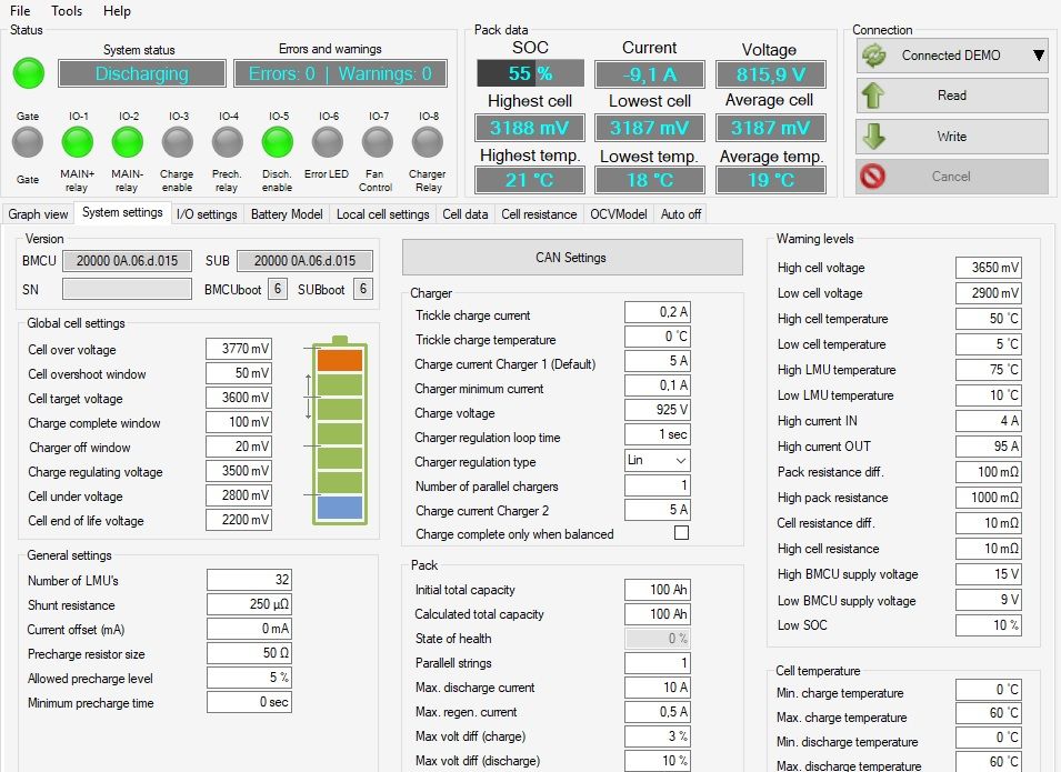
Rechargeable batteries by definition need charging and this makes charger control an important function for any battery management system. The s-BMS boasts of analog and pulse width modulation (PWM) control for charging as well as a library of CAN charger interfaces.
Safety is a primary function of any BMS. Whereas OEMs have access to benign chemistries such as high quality LiFePO4 – iron phosphate or LiMnO2 – manganese oxide based chemistries, others often opt for LiNiMnCoO2 (NCM) due to the high quality batteries available with this chemistry and its good balance of performance. Managing NCM cells is a zero tolerance activity as overcharging or any other event that leads to the battery overheating leads to thermal runaway whereby the vehicle/device is typically lost.

This puts a larger burden on the BMS to make absolutely sure that nothing goes wrong. Rapid response in such cases is paramount. The s-BMS in addition to the usual safety features has a dedicated hardware circuit that reacts in micro seconds to a short circuit event by engaging a semi conductor switch to shut off current. At least two levels of security are necessary during charging. Shutting down the charger in the event of a cell going into overvoltage is a first step, however, should the charger prove unresponsive, a second level of safety is required.

This can be opening a dedicated charger relay, which we at LiTHIUM BALANCE insist on. This, however is not always enough as certain charger types have a high inrush of current when connected to the battery pack, such that the charger relay can become welded over time unless it is protected by a pre-charge circuit, or over-dimensioned. The LiTHIUM Balance solution is to allow the customer to select a high voltage bus contactor to remain closed during charging, while the other is open. By connecting one leg of the charger circuit inside (battery side) of the HV contactors and the other outside (loadside), you can isolate the load during charging by opening one of the HV contactors and have the second one in the charging circuit as the final line of defence should all else fail.

Ground fault isolation

Leak detection or ground isolation fault detection is another key safety issue. The detection feature needs to be reliable and robust, avoiding triggering by noise and the presence of capacitive elements in the circuit, while still being able to reliably pinpoint real isolation faults and leaks to earth. We have taken ours a stage further whereby it is able to estimate where within the pack the leak is occurring.

Battery modelling

Tailoring the BMS to the exact needs of the cell type used in the pack allows the cells to be used reliably and optimally. The basics such as the cut off voltages and maximum charge and discharge currents, temperature windows for operation only give rough limits. Battery modelling allows you to extract more performance from the battery without adversely affecting lifespan or to extend life span at an existing performance level. By looking at the recommended performance window as a function of SoC and temperature, you can put in a first shot at the battery model.
Further testing allows these initial estimates to be further refined to produce a more accurate battery model. The end result will be a more accurate SoC estimation along with a better use of the batteries available power and energy. By incorporating this functionality into an easy to use GUI in the PC Diagnostic software, we have accelerated the whole process as now setting up the original model and updating it all take place onsite in the hands of the customer.

Battery kindness

The battery managment system, itself should neither drain or unbalance the pack, either during operation or when at rest. The LiTHIUM BALANCE s-BMS has the lowest power consumption in its class and draws power evenly from all connected cells preventing pack imbalance even if the system is left unused for months at a time.

Contactor control

Often, the last line of defense is opening the contactors when the battery pack or system finds itself in a critical fault condition. However, depending on the application, the nature of the fault and the BMS operational state, intelligence must be applied to the response. Opening the contactors of an electrical vehicle while driving along the highway due to a communication error or a momentary undervoltage would be seen as potentially dangerous, however, the same response would be appropriate for a stationary UPS solution where there is no human supervision of the system and interrupted communication could lead to cell over or under voltage. By making the errors on which contactor opening is triggered and the necessary persistence of the error, configurable, the safety responses of the system can be easily tailored to meet individual application requirements.

Conclusion

By combining flexibility with configurability the s-BMS has made it possible to meet the increasing demands of modern battery management without breaking the bank, or bursting a blood vessel. As with most elegant solutions, the goal is always to simplify the complex challenges using intelligence.

×
Call Now
Contact
Menu